C274 – ISO 5167 Sizing Calculation
Description
This calculates the flow element size of various differential pressure based flow meters according to the ISO 5167 technical standard.
References
ISO 5167: Measurement of fluid flows by means of pressure differential devices inserted in circular cross-section conduits running full
ISO TR9464: Guidelines for the use of ISO 5167
BS1042: Part 1. Pressure differential devices – Section 1.2 Specification for square-edged orifice plates and nozzles (with drain holes, in pipes below 50mm diameter, as inlet and outlet devices) and other orifice plates and Borda inlets (1984)
24509-54 – Flow Calculations for the V-Cone and Wafer-Cone Flow meters – McCrometer
24517-16 – V-Cone Flow Meter Technical Brief – McCrometer
Kelton calculation reference C274
Kelton calculation C270 – ISO 5167 Orifice Mass Flow Calculation
Kelton calculation C271 – ISO 5167 Venturi Mass Flow Calculation
Kelton calculation C272 – Cone Mass Flow Calculation
Kelton calculation C276 – ISO 5167-5:2016 Cone Mass Flow Calculation
Options
Meter Type
- Orifice
- Venturi
- V-Cone
- Wafer-Cone
- Cone (ISO 5167-5)
This option group allows selection of the meter type that the sizing calculation is to be performed on.
Standard version
Allows user to select from different revisions of the standard being applied.
Fluid
- Gas
- Liquid
This option allows selection of whether the fluid in question is a liquid or a gas.
Expansibility factor
- User entered
- Calculated
This option give the choice of calculating expansibility or entering a known value when the fluid is a gas.
For an orifice plate
Tapping Type
- Flange
- D/D2
- Corner
This option group allows the selection of the tapping type used for the pressure measurements on the orifice plate system.
Drain Hole
- None
- BS 1042
This option allows for selection of a drain hole correction according to BS 1042.
For venturi tubes and cones
Discharge coefficient
- User entered
- Variable with Reynold’s number
- Classical venturi with ‘as cast’ convergent section
- Classical venturi with rough-welded convergent section
- Classical venturi with a machined convergent section
- Venturi nozzle
- Uncalibrated Cone
This option allows the user to choose how discharge coefficient will be determined for a venturi tube. If a cone meter is selected only the first two options will be available for selection.
Exit cone angle
- 7°
- 15°
This option determines the equation used to calculate the permanent pressure loss associated with a venturi.
Calculation
Sizing Calculation
The orifice bore and venturi throat diameter are related to the diameter of the piping in the equation:

For cone meters the relationship is as follows:
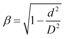
| Where | ||
|---|---|---|
| d | = | Flow element diameter |
| D | = | Pipe diameter |
The following relationships are applied in an iterative loop to solve for the flow element diameter at operating temperature.
For an orifice plate:
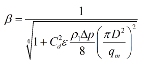
For a venturi tube:
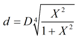
For V-cones and Wafer-cones:
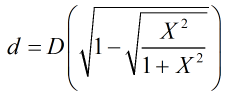
In these equations X is calculated by:
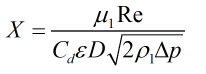
| Where | ||
|---|---|---|
| D | = | Pipe diameter |
| Δp | = | Differential pressure |
| ρ1 | = | Upstream density |
| Cd | = | Discharge coefficient |
| ε | = | Expansibility factor |
| μ1 | = | Dynamic viscosity |
| Re | = | Reynold’s number |
| qm | = | Mass flowrate |
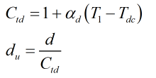
A temperature correction is then made to calculate the size of the flow element diameter at calibration temperature:
| Where | ||
|---|---|---|
| T1 | = | Upstream temperature |
| Tdc | = | Calibration temperature of the flow element |
| αd | = | Thermal expansion coefficient of flow element |
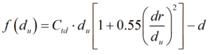
If a drain hole needs to be taken into account, orifice bore is calculated iteratively by employing a root finding algortihm around the equation:
| Where | ||
|---|---|---|
| dr | = | Drain hole diameter |
| du | = | Orifice bore at calibrated temperature |
| d | = | Orifice bore corrected for operating temperature |
| Ctd | = | Temperature correction |