ADC Input Check
Form
Form: K122 ADC Input check
Form Reference: C260
Purpose
The purpose of this test is to check the analogue inputs of a flow computer are converting the signal from the field instruments correctly.
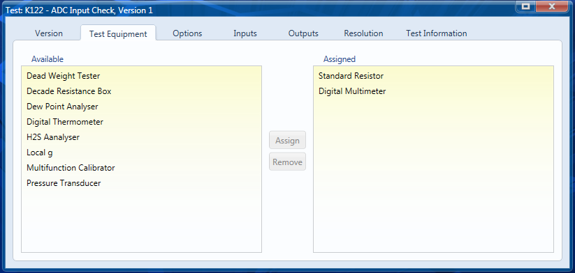
Test Equipment
A standard resistor and Digital Multimeter are selected for the test equipment. The calibrated value for the standard resistor is stored with the record for each available resistor so that the correct value will be used for the resistor selected during the test.
Options
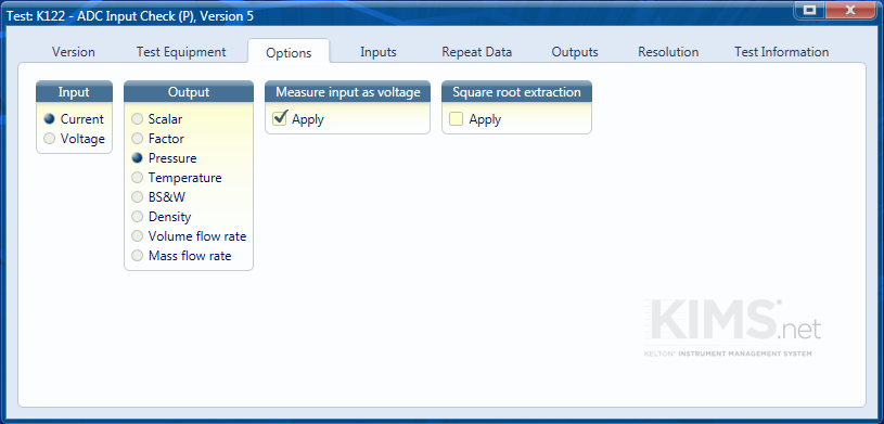
In this example we are checking the output of a 4mA – 20mA pressure transmitter is converted to the correct pressure value.
The current is measured as a voltage across a standard resistor and the calibrated value of the resistor is used.
The displayed pressure is read from the flow computer.
Inputs
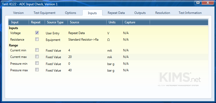
The measured voltage will be repeated as we will perform checks at increments throughout the range of the input.
The ‘Resistance’ will be set to take the actual value from the resistor in use.
The ‘Range’ Values will be fixed as they will not change between successive calibrations.
Repeat Data
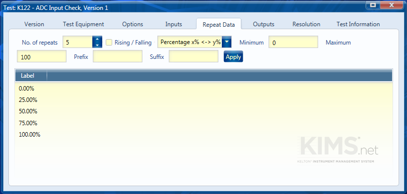
This test will generally be carried out over 5 points (25% intervals). The labels can be set automatically by selecting the options shown and clicking the ‘Apply’ button.
Outputs
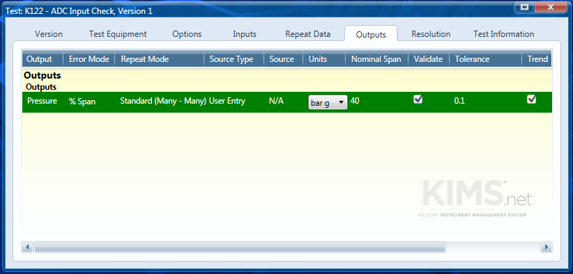
This form only has the one output ‘Pressure’ which corresponds to the variable selected in the ‘Options’ tab.
The error mode will be percentage of span
The repeat mode is the Standard (Many to Many) we will have a number of voltages and a number of pressures.
The units should be set to be the same as the variable range units and the nominal span set to be equal to the Pressure max – the pressure min.
A typical tolerance for an ADC Input Check will be 0.1 % of span.
