UN-302: Gas Orifice (NX-19 Density)
Description
Calculates the uncertainty in mass, standard volume and energy flowrate for a gas orifice meter run where gas density is calculated using NX-19 and a measured relative density value. Mass flowrate and density calculations and their uncertainties are performed using user-selectable calculations. Pressure and temperature uncertainties are determined using the technical specification for the transmitters selected from the integrated transmitter selection tool.
General
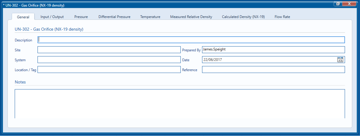
The General tab is used to enter information, which is saved along with the uncertainty calculation and included in reports which are generated.

The tabs used for inputting data and calculating the uncertainty in the individual components of the uncertainty can be seen along the top of the module window.
The report tab is only visible once the calculation has been run and will not be visible if any parameters are changed until the calculation has been run once more.
Input/Output
Options

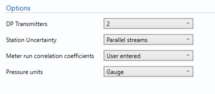
The options section controls how the calculation is performed and dictates which inputs are required.
DP transmitters
This option is used to select the number of differential pressure transmitters which are used in parallel. If two transmitters are selected an additional Differential Pressure will be displayed so that information can be entered on both high and low transmitters. If three DP transmitters are selected a third Differential Pressure tab will be included for the mid transmitter.
Station Uncertainty
By default the module will calculate the uncertainty for a single metering stream. If parallel streams are selected the Station Uncertainty will be calculated assuming the metering streams are nominally identical and the flow is split equally between the streams in use. When selecting parallel streams the correlation between inputs has to be considered and the user is presented with a further option to control how the correlation is defined.
Meter run correlation coefficients
If default is selected correlation coefficients which are considered to be typical of this type of meter will be used. Selecting User entered will enable the entry of correlation coefficients in the Flow Rates tab.
Pressure units
This section gives the option of entering the pressure as either an absolute value or as a gauge value with reference to atmospheric (barometric) pressure. If Absolute is selected inputs are required for Absolute pressure and Atmospheric pressure and if Gauge is selected inputs are required for Gauge pressure and Atmospheric pressure. This ensures that whichever is chosen both the gauge and Absolute pressure value is available to other sections of the module; for example the Density calculation tab may require an absolute pressure to perform the NX-19 calculation and the Gauge pressure may be used for the pressure transmitter calculation. Gauge pressure is equal to the Absolute pressure – the Atmospheric pressure.
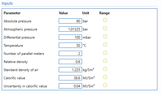
Inputs

Pressure
This is the line pressure of the gas stream measured upstream of the orifice plate. As described above, if Absolute is selected inputs are required for Absolute and Atmospheric pressure and if Gauge is selected inputs are required for Gauge and Atmospheric pressure.
Differential Pressure
This is the differential pressure measured across the orifice plate. If multiple transmitters are used the appropriate transmitter will be selected based on the transmitter ranges and the DP transmitter switch point.
DP Transmitter switch point
This option is only visible when multiple transmitters are selected and controls the selection of the transmitter which is deemed to be in-use for calculating the uncertainty. The switch Point is expressed as percentage of the span of the low transmitter. Consider the example where two transmitters are used; the low range transmitter has a range of 0 mbar to 125 mbar and the high range transmitter has a range of 0 mbar to 500 mbar. Setting the switch point to 95% will use the high range transmitter when the differential pressure is above 118.75 mbar (95% of the low range transmitter span)
Temperature
This is the measured temperature of the gas stream.
Number of parallel meters
This input is only visible when parallel streams are selected for the station uncertainty and refers to the number of in-use metering streams the flow is divided between.
Relative density
This is the relative density of the gas at standard conditions.
Standard density of air
This the density if air at standard reference conditions.
Calorific value
This is the calorific value of the gas.
Note: Calorific value is the energy produced by heating a known quantity to complete combustion.
Uncertainty in calorific value
This is the uncertainty associated with the calorific value of the gas.
Outputs

The outputs section shows the calculated flow rate and uncertainty taken from the Flow Rate tab.
Calculation Tabs
The following tabs are used within this uncertainty module: