BL-301 – Orifice Plate – Gas Flow Rate
Description
This block calculates the uncertainty in gas flow rate for an orifice plate where mass flow rate is determined in accordance with AGA Report No.3 or the ISO 5167 standard.
Options
Reference
- ISO 5167
- AGA 3
This option is used to select which standard is to be used.
ISO 5167
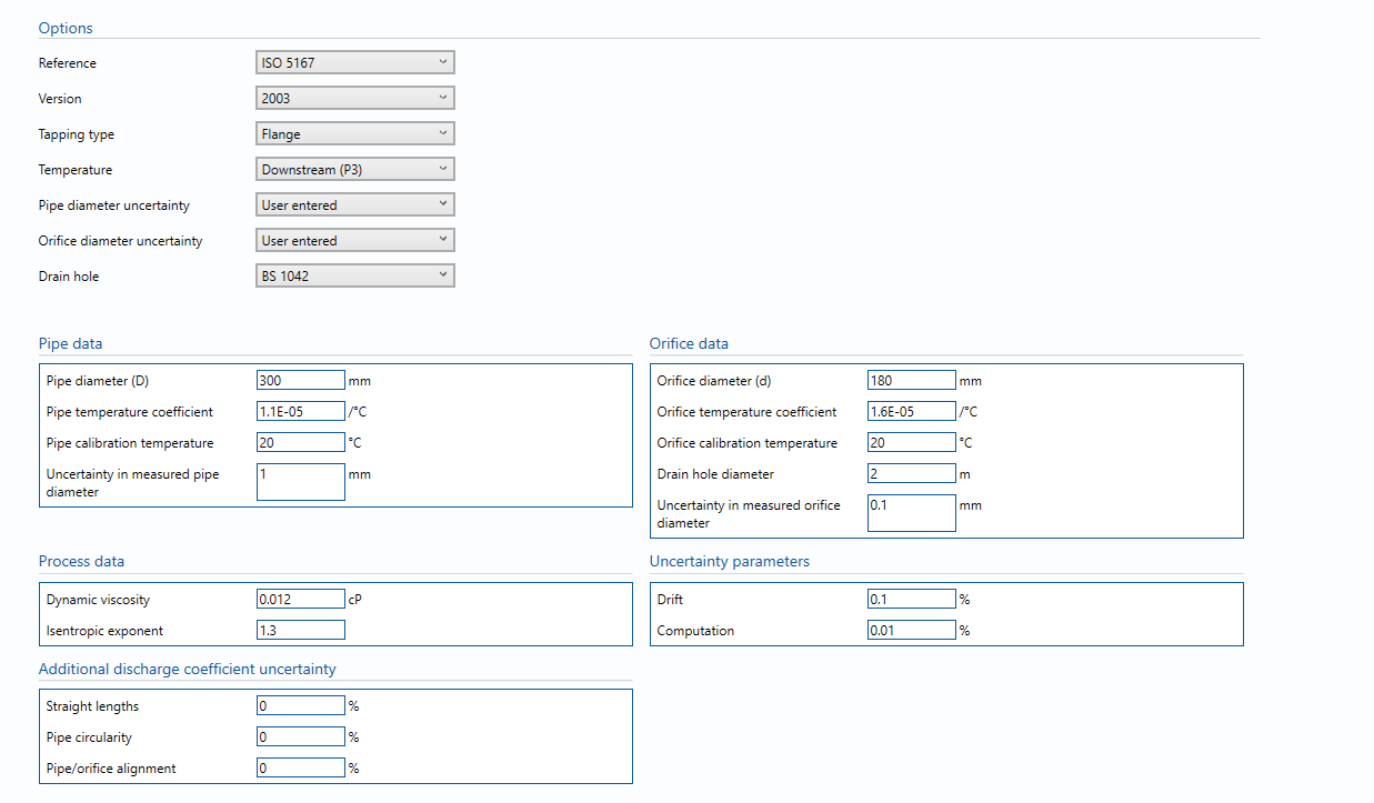
Version
- 1991
- 1998
- 2003
This option is used to select the version of ISO 5167 used to calculate flow rate.
Tapping Type
- Flange
- D/D2
- Corner
This option is used to select what type of pressure tapping is used.
Temperature
- Upstream (P1)
- Downstream (P3)
This option is used to select whether the input temperature has been measured upstream or at the downstream recovery point.
Pipe diameter uncertainty
- user entered
- standard default
This option is used to select whether the pipe diameter is entered manually or set according the limit given in the standard.
Orifice diameter uncertainty
- user entered
- standard default
This option is used to select whether the orifice diameter is entered manually or set according the limit given in the standard.
Drain hole
- BS 1042
- None
This option is to specify for a drain hole correction (according to BS 1042/ISO TR 15377) in the orifice flow rate calculation. If there is no drain hole None is to be selected.
Inputs
Pipe data
Pipe diameter – Measured pipe bore diameter.
Pipe temperature coefficient – Thermal expansion coefficient of pipe material.
Pipe calibration temperature – Temperature at which pipe diameter measurement was made.
Uncertainty in measured pipe diameter – uncertainty in the measurement made of the pipe diameter
Note: Last input only available if used entered is selected from the Pipe diameter uncertainty option.
Orifice data
Orifice diameter – Measured orifice bore diameter.
Orifice temperature coefficient – Thermal expansion coefficient of orifice material.
Orifice calibration temperature – Temperature at which orifice diameter measurement was made.
Drain hole diameter – Diameter of drain hole.
Uncertainty in measured orifice diameter – uncertainty in the measurement of the orifice diameter
Note: Last input only available if used entered is selected from the Orifice diameter uncertainty option.
Uncertainty parameters
Drift – Allowance for drift due to plate damage or rounding. Normally left at zero, unless evidence is present to suggest a higher value.
Computation – Uncertainty due to computational errors in flow computer.
Additional discharge coefficient uncertainty
Straight lengths – Additional uncertainty due to insufficient upstream straight lengths. Information can be obtained from ISO 5167 and ISO TR 12767 if applicable.
Pipe circularity – Additional uncertainty due to poor upstream pipe circularity lengths. Information can be obtained from ISO 5167 if applicable.
Pipe/orifice alignment – Additional uncertainty due to poor orifice/pipe alignment. Information can be obtained from ISO 5167 if applicable.
Process Data
Dynamic viscosity – the measurement of internal resistance force of the gas flowing.
Isentropic exponent – the ratio of the specific heat at constant pressure to the specific heat at constant volume.
AGA 3
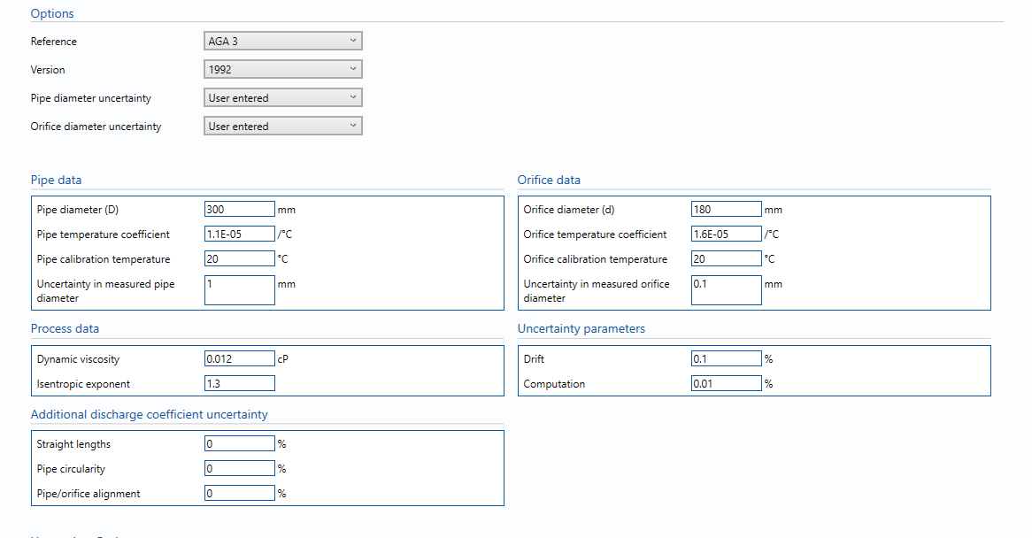
Version
- 1992
- 2012
This option is used to select the version of AGA 3 that is to be used, if AGA 3 is selected otherwise the options used are as follows.
Pipe diameter uncertainty
- user entered
- standard default
This option is used to select whether the pipe diameter is entered manually or set according the limit given in the standard.
Orifice diameter uncertainty
- user entered
- standard default
This option is used to select whether the orifice diameter is entered manually or set according the limit given in the standard.
Pipe data
Pipe diameter – Measured pipe bore diameter.
Pipe temperature coefficient – Thermal expansion coefficient of pipe material.
Pipe calibration temperature – Temperature at which pipe diameter measurement was made.
Uncertainty in measured pipe diameter – uncertainty in the measurement made of the pipe diameter
Note: Last input only available if used entered is selected from the Pipe diameter uncertainty option.
Orifice data
Orifice diameter – Measured orifice bore diameter.
Orifice temperature coefficient – Thermal expansion coefficient of orifice material.
Orifice calibration temperature – Temperature at which orifice diameter measurement was made.
Drain hole diameter – Diameter of drain hole.
Uncertainty in measured orifice diameter – uncertainty in the measurement of the orifice diameter
Note: Last input only available if used entered is selected from the Orifice diameter uncertainty option.
Uncertainty parameters
Drift – Allowance for drift due to plate damage or rounding. Normally left at zero, unless evidence is present to suggest a higher value.
Computation – Uncertainty due to computational errors in flow computer. Negligible term included for completeness – assume 0.01%.
Additional discharge coefficient uncertainty
Straight lengths – Additional uncertainty due to insufficient upstream straight lengths. Information can be obtained from ISO 5167 and ISO TR 12767 if applicable.
Pipe circularity – Additional uncertainty due to poor upstream pipe circularity lengths. Information can be obtained from ISO 5167 if applicable.
Pipe/orifice alignment – Additional uncertainty due to poor orifice/pipe alignment. Information can be obtained from ISO 5167 if applicable.
Process Data
Dynamic viscosity – the measurement of internal resistance force of the gas flowing.
Isentropic exponent – the ratio of the specific heat at constant pressure to the specific heat at constant volume.
Calculations
The gas flow rates (mass, standard volume & energy) are calculated using the selected version of ISO 5167 using C280 – ISO 5167 Orifice Calculations. If AGA 3 is selected the gas flow rates (mass, standard volume & energy) are calculated using the selected version of AGA 3 using either C266 – AGA3:1992 – Orifice Flow Calculation or C285 – AGA3:2012 – Orifice Flow Calculation.
The differential pressure, line density, standard density and calorific value uncertainties are taken from the blocks B002 – Differential Pressure, B005 – Calculated Gas Density, B006 – Calculated Gas Standard Density and B008 – Calorific Value respectively. The pressure and temperature will be taken from the Input/output tab and the expanded uncertainties for these used will be as calculated in blocks B001 – Pressure and B003 – Temperature.
The units selected for parameters on the Input/Output tab will be applied globally throughout the uncertainty module in use. They will be applied to values used in the uncertainty budget. Inputs that are local to this block can have their units altered within the block.
Mass flow rate
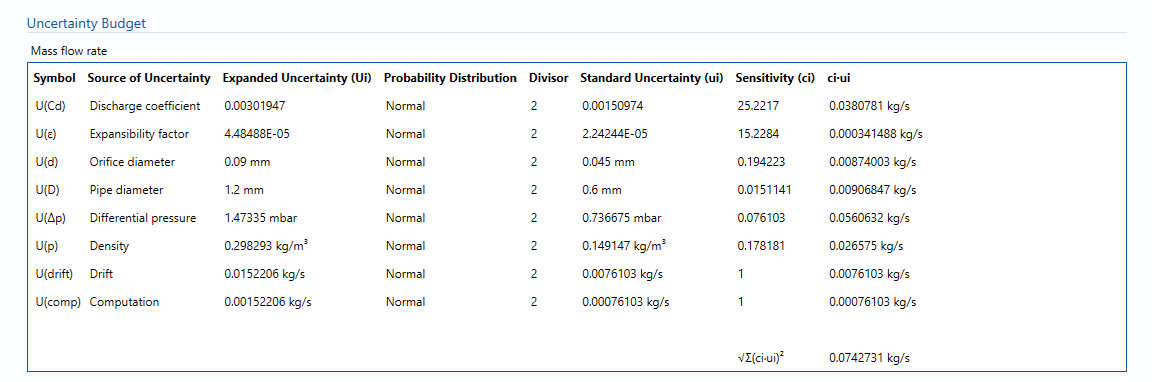
The uncertainty calculation for the mass flow rate is detailed in the first uncertainty budget table giving a break down of how the overall uncertainty is calculated. The values input into the uncertainty budget are taken from the module inputs and calculations from other blocks along with the uncertainty components calculated in this block from the calculation inputs. The differential pressure and its uncertainty are taken from the block B002 – Differential Pressure. The gas density and its uncertainty are taken from the block B005 – Calculated Gas Density. Uncertainties associated with these values are taken in as the expanded uncertainties and are divided by a coverage factor to gain the standard uncertainty. The coverage factor is determined by the probability distribution that best suits that uncertainty component. The standard uncertainty is then multiplied by the sensitivity value then squared. This is done for each component that contributes to the overall uncertainty in mass flow rate. The standard absolute uncertainty in mass flow rate is the square root of the sum of each component variance. This is multiplied by the coverage factor obtain the expanded absolute uncertainty in mass flow rate. The coverage factor is defaulted to k = 2 so that a confidence level above 95% is achieved. The expanded absolute uncertainty is then divided by the mass flow rate value to obtain the expanded relative uncertainty.
The sensitivity coefficients for each of these input uncertainties are derived from the equation set out in ISO 5167-1:2003 section 8.2.2.1 & ISO 5167-1:1991 section 11.2.2.
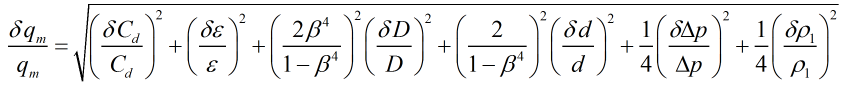
The sensitivity coefficients for AGA 3 are derived from equation (1-36) which is equivalent to the above.
Standard volume flow rate
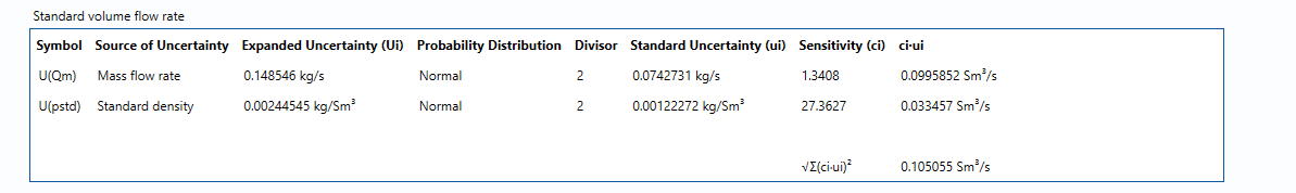
The uncertainties in mass flow rate and standard density are taken into the uncertainty budget. The standard density and its uncertainty are taken from the block B006 – Calculated Gas Standard Density. The sensitivity values are generated from the mass flow rate and standard density and are multiplied by the standard uncertainty and then squared. The standard absolute uncertainty in standard volume flow rate is the square root of the sum of each component variance. This is multiplied by the coverage factor obtain the expanded absolute uncertainty in standard volume flow rate. The coverage factor is defaulted to k = 2 so that a confidence level above 95% is achieved. The expanded absolute uncertainty is then divided by the standard volume flow rate value to obtain the expanded relative uncertainty.
Energy flow rate
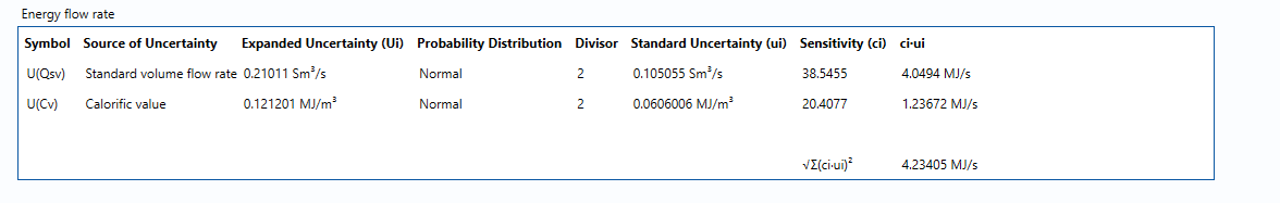
The uncertainties in standard volume flow rate and calorific value are taken into the uncertainty budget. The calorific value and its uncertainty are taken from the block B008 – Calorific Value. The sensitivity values are generated from the standard volume flow rate and calorific value and are multiplied by the standard uncertainty and then squared. The standard absolute uncertainty in energy flow rate is the square root of the sum of each component variance. This is multiplied by the coverage factor obtain the expanded absolute uncertainty in energy flow rate. The coverage factor is defaulted to k = 2 so that a confidence level above 95% is achieved. The expanded absolute uncertainty is then divided by the energy flow rate value to obtain the expanded relative uncertainty.
Calculated Uncertainty
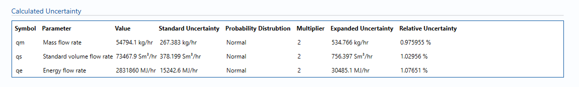
The Expanded Uncertainty is the Standard Uncertainty multiplied by the coverage factor (k). The coverage factor is defaulted to k = 2 (equivalent to a confidence level of approximately 95%).
The Relative Uncertainty is the Expanded Uncertainty divided by the mass flow rate or standard volume flow rate or energy flowrate depending on the parameter.
References
Standards
ISO 5168:2005 – Measurement of fluid flow – Procedures for the evaluation of uncertainties
ISO Guide 98-3 – Uncertainty of measurement – Part 3: Guide to the expression of uncertainty in measurement (GUM:1995)
ISO 5167-1:1991 – Measurement of fluid flow by means of pressure differential devices – Part 1: Orifice plates, nozzles and venturi tubes inserted in circular cross-section conduits running full
ISO 5167-1:1991/Amd 1:1998 – Measurement of fluid flow by means of pressure differential devices – Part 1: Orifice plates, nozzles and venturi tubes inserted in circular cross-section conduits running full
ISO 5167-1:2003 – Measurement of fluid flow by means of pressure differential devices inserted in circular cross-section conduits running full – Part 1: General principles and requirements
ISO 5167-2:2003 – Measurement of fluid flow by means of pressure differential devices inserted in circular cross-section conduits running full – Part 2: Orifice plates
ISO TR 9464:1998 – Guidelines for the use of ISO 5167:1991
ISO TR 9464:2008 – Guidelines for the use of ISO 5167:2003
ISO TR 12767:1998 – Measurement of fluid flow by means of pressure differential devices – Guidelines on the effect of departure from the specifications and operating conditions given in ISO 5167
ISO TR 12767:2007 – Measurement of fluid flow by means of pressure differential devices – Guidelines on the effect of departure from the specifications and operating conditions given in ISO 5167
ISO TR 15377:1998 – Measurement of fluid flow by means of pressure differential devices – Guidelines for the specification of nozzles and orifice plates beyond the scope of ISO 5167
ISO TR 15377:2007 – Measurement of fluid flow by means of pressure differential devices – Guidelines for the specification of orifice plates, nozzles and venturi tubes beyond the scope of ISO 5167
AGA Report No.3 – Orifice Metering of Natural Gas and Other Related Hydrocarbon Fluids – Concentric, Square-edged Orifice Meters – Part 1: General Equations and Uncertainty Guidelines (1990)
AGA Report No.3 – Orifice Metering of Natural Gas and Other Related Hydrocarbon Fluids – Concentric, Square-edged Orifice Meters – Part 2: Specification and Installation Requirements (2000)
AGA Report No.3 – Orifice Metering of Natural Gas and Other Related Hydrocarbon Fluids – Concentric, Square-edged Orifice Meters – Part 3: Natural Gas Applications (1992)
AGA Report No.3 – Orifice Metering of Natural Gas and Other Related Hydrocarbon Fluids – Concentric, Square-edged Orifice Meters – Part 4: Background, Development, Implementation Procedure, and Subroutine Documentation for Empirical Flange-Tapped Discharge Coefficient Equation (1992)
AGA Report No.3 – Orifice Metering of Natural Gas and Other Related Hydrocarbon Fluids – Concentric, Square-edged Orifice Meters – Part 1: General Equations and Uncertainty Guidelines (2012)
KCCL Calculations
C280 – ISO 5167 Orifice Calculations
C266 – AGA3:1992 – Orifice Flow Calculation
C285 – AGA3:2012 – Orifice Flow Calculation