C272 – Cone Meter Mass Flow Calculation
Description
This calculates the mass flowrate for cone type differential pressure based meters.
References
ISO 5167: Measurement of fluid flow by means of pressure differential devices inserted in circular cross-section conduits running full
ISO TR9464: Guidelines for the use of ISO 5167
24509-54 Flow Calculations for the V-Cone and Wafer-Cone Flow meters – McCrometer
24517-16 V-Cone Flow Meter Technical Brief – McCrometer
Kelton calculation reference C272
Kelton calculation C282: V-cone Calculations
Kelton calculation C150: Upstream Density Calculation
Options
Fluid
- Gas
- Liquid
This option allows selection of whether the fluid in question is a liquid or a gas.
Discharge Coefficient
- User entered
- Variable with Reynold’s number
This option allows the user to enter a known discharge coefficient or calculate it against Reynold’s number using linear interpolation.
Cone Type
- V-Cone
- Wafer Cone
This option group gives the choice between a wafer cone and a v-cone meter.
Standard Version
- 2000
- 2005
This option group allows selection of the year of McCrometer technical publications with regard to their v-cone meters. The wafer-cone meter is not referred to in the earlier technical publication.
Expansibilty Factor
- User entered
- Calculated
This option gives the choice for expansibility factor to be entered by the user or calculated.
Temperature
- Upstream
- Downstream
This option allows selection of where the temperature is measured, upstream of the orifice plate meter or downstream where the flow has fully recovered.
Temperature Referral
- Isentropic
- Isenthalpic
This option group will appear if downstream temperature is selected. It allows a choice between an isentropic or an isenthalpic correction to upstream temperature.
Joule-Thomson Coefficient
- User entered
- Calculated
This option group will appear if an isenthalpic correction to upstream temperature is selected, it allows the Joule-Thomson coefficient to be entered if the value is known or calculated by Reader-Harris’ simplified equation if otherwise.
Density
- Upstream
- Downstream
This option group allows selection where the density measurement is taken, upstream of the orifice plate or downstream at pressure, p2, and temperature T3.
Density Referral
- Isentropic
- Isenthalpic
This option group will appear if the downstream density option is selected. It allows a choice of whether density is corrected to upstream conditions using an isentropic or isenthalpic (PTZ) correction as shown in F037.
Calculation
Mass Flowrate
The mass flowrate is calculated by:

| Where | ||
|---|---|---|
| Cd | = | Discharge coefficient |
| β | = | Beta ratio |
| ε | = | Expansibility factor |
| d | = | Cone diameter |
| Δp | = | Differential pressure |
| ρ1 | = | Upstream density |
Beta Ratio
The beta ratio is calculated by:
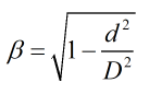
| Where | ||
|---|---|---|
| d | = | Cone diameter |
| D | = | Pipe diameter |
Discharge Coefficient
If the variable with discharge coefficient is selected a series of experimentally determined discharge coefficients with the accompanying Reynold’s numbers will be required to be input. An initial estimate of Reynold’s number will be used to calculate a discharge coefficient from the provided data using linear interpolation, from this mass flowrate is then estimated and then Reynold’s number. This forms an iterative loop to determine discharge coefficient, Reynold’s number and mass flowrate.
Expansibility Factor
For a V-cone flow meter the expansibility is calculated using the venturi expansibility equation if the option to use the 2000 McCrometer paper is selected otherwise it is calculated by:

For a wafer cone flow meter the expansibility is calculated by:

Pressure Loss
The permanent pressure loss across a cone meter is calculated from the equation:
![]()
Temperature Referral
The temperature referral employed is the same as can be seen here.