Liquid Orifice Plate flow Rate
Options
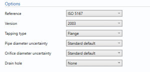
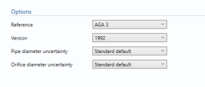
Reference
- ISO 5167
- AGA 3
Select the reference used for calculation.
Version
- 1991
- 1998
- 2003
If ISO 5167 is selected
- 1992
- 2012
If AGA 3 is selected
Tapping type
- Flange
- D/D2
- Corner
Select the tapping type in the orifice meter.
Note: Only required if ISO 5167 is selected.
Pipe diameter uncertainty
- User Entered
- Standard default
Select if the uncertainty in pipe diameter is user enter or set to standard default.
Note: the value of the standard default depends on the reference standard selected.
Orifice diameter uncertainty
- User Entered
- Standard default
Select if the uncertainty in orifice diameter is user enter or set to standard default.
Note: the value of the standard default depends on the reference standard selected.
Drain Hole
- None
- BS 1042
Select the drain hole requirement in the liquid orifice meter.
Note: Only required if ISO 5167 is selected.
Pipe data
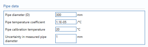
Pipe diameter – enter the diameter of the pipe.
Pipe temperature coefficient – Enter the temperature coefficient for the pipe.
Temperature coefficient shows the change in the physical property that is caused by a change in temperature.
Pipe calibration temperature – Enter the temperature at which the pipe is calibrated.
Uncertainty in measured pipe diameter – Enter the uncertainty in the measurement of the pipe diameter.
Note: This option is available if user entered is selected from the options.
Process data
![]()
Dynamic viscosity – Enter Dynamic viscosity in the flow.
Dynamic Viscosity is the force that the fluid’s internal resistance exerts on the flow.
Orifice data
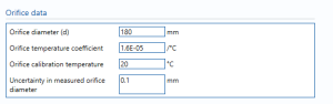
Orifice diameter – Enter the diameter of the orifice.
Orifice temperature coefficient – Enter the temperature coefficient for the orifice meter.
Temperature coefficient shows the change in the physical property that is caused by a change in temperature.
Orifice calibration temperature – Enter the temperature at which the orifice is calibrated.
Uncertainty in measured orifice diameter – Enter the uncertainty in the measurement of the pipe diameter.
Note: This option is available if user entered is selected from the options.
Uncertainty parameters
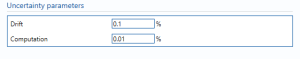
Drift – Additional uncertainty allowance due to meter drift from factors such as time, ambient temperature and line voltage. Normally left at zero, unless evidence is present to suggest a higher value.
Note: Drift is rarely apparent but needs to be continuously monitored through inspection, prevention and maintenance.
Computation – Uncertainty due to computational errors in flow computer.
Additional discharge coefficient uncertainty
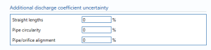
Straight lengths – Enter the percentage uncertainty due to straight lengths.
Pipe circularity – Enter the percentage uncertainty due to pipe circularity.
Pipe/Orifice alignment – Enter the percentage uncertainty due to alignment.
Uncertainty Budget
Mass flow rate
The uncertainty calculation for the mass flow rate is detailed in the uncertainty budget table giving a break down of how the overall uncertainty is calculated. The values input into the uncertainty budget are taken from the module inputs and calculations from other blocks along with the uncertainty components calculated in this block from the calculation inputs.
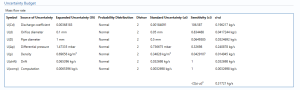
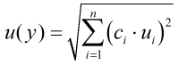
The coverage factor is determined by the probability distribution that best suits that uncertainty component. The standard uncertainty is then multiplied by the sensitivity value then squared. This is done for each component that contributes to the overall uncertainty in mass flow rate. The Standard Uncertainty in mass flow rate is the square root of the sum of each component variance as shown in the following equation:
Standard volume flow rate
The uncertainty budget table shows a break down of the different components that contribute to the overall calculated uncertainty.
![]()
The values input into the uncertainty budget are derived from the different blocks and the transmitter specific values relating to the calibration and specification. These values are taken in as the expanded uncertainties and are divided by a coverage factor to gain the standard uncertainty.
The coverage factor is determined by the probability distribution that best suits that uncertainty component. The standard uncertainty is then multiplied by the sensitivity value then squared. This is done for each component that contributes to the overall uncertainty in standard volume flow rate. The Standard Uncertainty in the standard volume flow rate is the square root of the sum of each component variance as shown in the following equation:
Calculated Uncertainty
![]()
The Expanded Uncertainty is the Standard Uncertainty multiplied by the coverage factor (k). The coverage factor is defaulted to k = 2 (equivalent to a confidence level of approximately 95%).
The Relative Uncertainty is the Expanded Uncertainty divided by the mass flow rate or standard volume flow rate depending on the parameter.