Gas Venturi (Calc dens, Calc Std dens, Calc CV)
Options
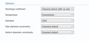
Discharge coefficient
- User entered
- Classical Venturi with ‘as cast’ convergent section.
- Classical Venturi with rough-welded convergent section.
- Classical Venturi with a machined convergent section.
- Venturi nozzle
Select the way to input the discharge coefficient as per ISO 5167.
Temperature
- Upstream
- Downstream
Select if the temperature is measured downstream or upstream of the Venturi.
Standard
- 1991
- 2003
Select the year of the standard to be used in the calculations.
Pipe diameter uncertainty
- User entered
- Standard default
Enter whether the diameter of the pipe is user entered or the standard default.
Venturi diameter uncertainty
- User entered
- Standard default
Enter whether the diameter of the Venturi is user entered or the standard default.
Pipe data
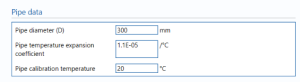
Pipe diameter (D) – Enter the diameter of the pipe.
Pipe temperature expansion coefficient – Enter the temperature expansion coefficient.
Note: the coefficient of expansion represents the change in size with respect to temperature.
Pipe calibration temperature – Enter the temperature at which the pipe was calibrated.
Uncertainty parameters

Dynamic viscosity – the dynamic viscosity of the flow in the stream.
Note: Dynamic viscosity is the measure of the resistance to internal force of the fluid.
isentropic exponent – the isentropic exponent of gas.
Note: isentropic exponent is the ratio of the specific heat at constant pressure to specific heat at constant volume.
Venturi data
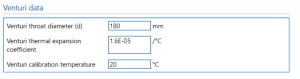
Venturi throat diameter (d) – Enter the throat diameter for the Venturi.
Venturi thermal expansion coefficient – the thermal expansion coefficient of the Venturi.
Note: thermal expansion coefficient is the change in size per unit change in temperature.
Venturi calibration temperature – the temperature at which the Venturi is calibrated.
Process data
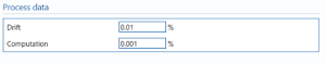
Drift – Additional uncertainty allowance due to meter drift from factors such as time, ambient temperature and line voltage. Normally left at zero, unless evidence is present to suggest a higher value.
Note: Drift is rarely apparent but needs to be continuously monitored through inspection, prevention and maintenance.
Computation – Uncertainty due to computational errors in flow computer.
Additional discharge coefficient uncertainty
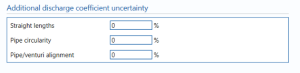
straight lengths – enter the percentage uncertainty due to straight lengths in pipe.
Pipe circularity – enter the percentage uncertainty due to circularity of the pipe.
Pipe/orifice alignment – enter the percentage uncertainty due to the alignment of the pipe and the orifice.
Calculations
The uncertainty for the mass flow rate, standard volume flow rate and energy flow rate are calculated.
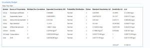
Uncertainty Budget
The uncertainty calculation is detailed in the uncertainty budget tables for the uncorrected mass flow rate, standard volume flow rate and energy flow rate giving a break down of how the overall uncertainty is calculated for that parameter.
![]()
![]()
Uncertainties associated with these values are taken in as the Expanded Uncertainties. The Standard Uncertainty is calculated from dividing the Expanded Uncertainty by the coverage factor which is determined by the probability distribution that best suits that uncertainty component.
The Standard Uncertainty is then multiplied by the sensitivity value then squared. This is done for each parameter that contributes to the overall uncertainty in that parameter. The Standard Uncertainty in the parameter is the square root of the sum of each component variance as shown in the following equation:
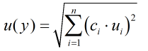
Calculated Uncertainty
![]()
The Expanded Uncertainty is the Standard Uncertainty multiplied by the coverage factor (k). The coverage factor is defaulted to k = 2 (equivalent to a confidence level of approximately 95%). The Relative Uncertainty is the Expanded Uncertainty divided by mass flow rate, standard volume flow rate or energy flow rate depending on the parameter.