C266 – AGA 3:1992 Orifice Plate Flow Calculation
Description
This calculates the flow rate measured through an orifice plate metering system. The calculation can also be rearranged to solve the differential pressure across an orifice plate or the bore diameter.
References
AGA Report No. 3 – Orifice Metering of Natural Gas and Other Related Hydrocarbon Fluids/Manual of Petroleum Measurement Standards Chapter 14 – Natural Gas Fluids Measurement Section 3 – Concentric, Square-Edged Orifice Meters:
Part 1 – General Equations and Uncertainty Guidelines (Third Edition, September 1990)
Part 3 – Natural Gas Applications (Third Edition, August 1992)
Part 4 – Background, Development, Implementation Procedures and Subroutine Documentation (Third Edition, November 1992)
Kelton calculation reference C266
FLOCALC calculation reference F074
KIMS Calculation reference K126
Options
Fluid
- Gas
- Liquid
This option is used to select whether the fluid is liquid or a gas. If it is liquid the expansibility factor will be set to 1.
Solve for
- Flow
- Orifice size
- Differential pressure
This option is used to select the desired output of the calculation.
Pressure
- Measured at upstream tap (P1)
- Measured at downstream tap (P2)
This option is available when solving for flow rate. It allows the user the option of inputting pressure at either the upstream or downstream tap.
Solution method
- Direct substitution
- Newton-Raphson
This option is used to select the method of calculation used to gain the flow rate. Both methods are generally acceptable to use though the Newton-Raphson converges faster. The direct substitution method should not be used for high viscosity liquids.
Method
- Developed from the density of fluid
- Developed from the real gas relative density
This option allows the user to select which set of inputs they wish to use for implementation of the AGA 3 flow rate equations. Both sets have common inputs such as geometry of the system and differential pressure, dynamic viscosity etc, but the first requires line density, the second uses real gas relative density along with PTZ data.
The remaining options will be drawn are seen in C261 or C262 and depend on the fluid used.
Calculate for
- Mass
- Observed volume
- Standard volume
- Normal volume
- Energy
Calculate from
- Mass
- Observed volume
- Standard volume
- Normal volume
This option becomes active if solving for an orifice size or differential pressure
Constants
Molecular mass of air – Mair = 28.9625 g/mol
Gas constant – R = 8.314472 J/molK
Calculation
Mass flow rate
Mass flow rate as calculated ‘from the density of the fluid’ is derived from equation 3-1 in AGA 3 Part 3.

| Where | ||
|---|---|---|
| Cd | = | Coefficient of discharge |
| Ev | = | Velocity of approach factor |
| Y1 | = | Expansibility factor |
| d | = | Orifice diameter |
| Δp | = | Differential pressure |
| ρ | = | Line density |
Standard volume flow rate
Standard volume flow rate as calculated ‘from the real gas relative density’ is done derived from equation 3-6a in AGA 3 Part 3.

| Where | ||
|---|---|---|
| Cd | = | Coefficient of discharge |
| Ev | = | Velocity of approach factor |
| Y1 | = | Expansibility factor |
| d | = | Orifice diameter |
| Tb | = | Base temperature |
| Pb | = | Base pressure |
| Mair | = | Molecular weight of air |
| R | = | Gas Constant |
| P | = | Line pressure |
| Z | = | Line compressibility |
| Zb | = | Base compressibility |
| Zbair | = | Base compressibility of air |
| T | = | Line temperature |
| Gr | = | Real gas relative density |
| Δp | = | Differential pressure |
Coefficient of Discharge
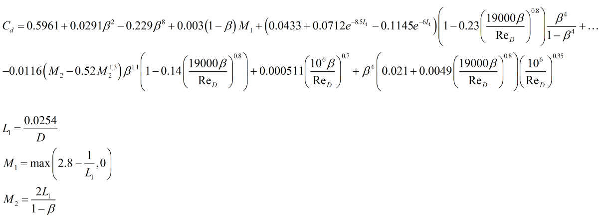
AGA 3 uses the Reader-Harris Gallagher equation for the calculation of coefficient of discharge, Cd, this is derived from equations 3-11 through to 3-21 in AGA 3 Part 3 and is as follows.

| Where | ||
|---|---|---|
| β | = | Diameter ratio |
| ReD | = | Reynolds number |
| D | = | Pipe diameter in meters |
Expansion Factor
AGA 3:1992 uses the Buckingham and Bean equation which is as follows:

| Where | ||
|---|---|---|
| P | = | Line pressure |
| Δp | = | Differential pressure |
| β | = | Diameter ratio |
| k | = | Isentropic exponent |
Velocity of Approach Factor
The velocity of approach factor is calculated by:

| Where | ||
|---|---|---|
| β | = | Diameter ratio |