C099 – ISO 3171:1999 Annex A – Estimating Water-in-Oil Dispersion
Description
This calculation can be used for various piping configurations to indicate whether the dispersion of water in oil is likely to be adequate for sampling to take place.
References
BS EN ISO 3171:1999 – Petroleum liquids – Automatic pipeline sampling
Kelton calculation reference C099
FLOCALC calculation reference F095
Options
Calculate
- Required Energy
- Water concentration ratio (C1/C2)
This option is used to select whether to calculate the water concentration ratio or the required energy for dispersion.
Method
- Method A
- Method B
This option is used to select how the energy available will be calculated.
Piping Element (Method A)
- Contraction
- Enlargement
- Orifice
- Circular mitre bends
- Swing check valve
- Angle valve
- Globe valve
- Gate valve
This option is used to select the piping element under consideration when Method A is selected.
Piping Element (Method B)
- Contraction
- Enlargement
- Bends
- Centrifugal pump
- Throttling valve
- Flow nozzle
- Straight pipe
This option is used to select the piping element under consideration when Method B is selected.
Pressure Drop
- User entered
- Calculated
If Method A is selected then the pressure drop across the piping element can be user entered or calculated.
Dissipation Distance
- User entered
- Calculated
If Method A is selected then this option is used to specify whether the dissipation distance is user entered or calculated.
No. of Bends
- 1
- 2
- 3
- 4
- 5
If bends is selected from the Method B list then this option is used to specify the number of bends in the pipe.
Calculation
Flow Velocity
The velocity of the flow through the pipe is calculated by:
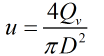
| Where | ||
|---|---|---|
| Qv | = | Gross volumetric flow rate |
| D | = | Pipe diameter |
Dissipation Distance
In most cases the distance in which the energy has dissipated is not known. Wherever possible the value used should be supported by experimental data. If ΔX is not known it is calculated using the approximation:
![]()
Pressure Drop
The pressure drop across the piping element is calculated by:
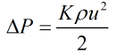
| Where | ||
|---|---|---|
| ρ | = | Liquid density |
| K | = | Resistance coefficient of piping element |
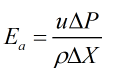
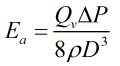
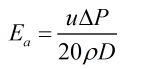
Energy Available
Method A
If Method A is selected then the energy available for dispersion is calculated by:
Method B
For Contractions, enlargements and Bends
For these elements the energy available for dispersion is calculated by:
![]()
| Where | ||
|---|---|---|
| β | = | Characteristic parameter of mixing element |
| E0 | = | Energy dispersion for a straight pipe |
Centrifugal Pump
If the element selected from the method B list is a centrifugal pump then energy available for dissipation is calculated by:
Throttle Valve
If the element selected from the method B list is a throttling valve then energy available for dissipation is calculated by:
Flow Nozzle
If the element selected from the method B list is a nozzle then energy available for dissipation is calculated by:
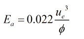
| Where | ||
|---|---|---|
| φ | = | Nozzle diameter |
| ue | = | Velocity at nozzle exit |
Turbulence characteristic
The turbulence characteristic is calculated from the relationship:
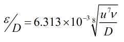
| Where | ||
|---|---|---|
| ν | = | Kinematic viscosity |
| u | = | Flow velocity |
Settling Rate
The settling rate found via the relationship:
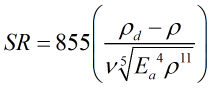
| Where | ||
|---|---|---|
| ρd | = | Water density |
Energy Required
The energy required for dissipation is calculated from the relationship:
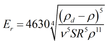
If the energy required is less than the energy available then it follows that mixing has not been sufficient for adequate sampling to take place.