C260 – ADC Input
Description
This calculation performs an ADC check which can be used for the calibration of equipment where there is a linear relationship between the input quantity and the output.
References
Kelton calculation reference C260
KIMS calculation reference K122
Options
Transmitter Input
- Current
- Voltage
This option allows user to select whether the input is a current or a voltage.
Transmitter Output
- Scalar
- Factor
- Pressure
- Temperature
- BS&W
- Volume flow rate
- Mass flow rate
This option allows user to select the relevant output type.
Measure input as voltage
Allows user to input a voltage which is then converted to a current using Ohm’s law.
Measure input as current
Allows user to input a current which is then converted to a voltage using Ohm’s law.
Square root extraction
This option is selected if the input has a square root relationship with the output.
Linearise as input approaches LRV
This option is selected to linearise the square root extraction function for values very close to or below the lower range value.
Calculation
Output Value
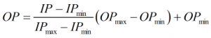
The output value is calculated by:
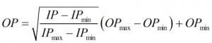
Or when square root extraction is applied:
When the input is less than 0.6% the input range the above linear function is used. When the input is above 0.8% of the input range the normal square root extraction function, as detailed above, is used. When square root extraction is linearised the following function is used when the input is between 0.6 and 0.8% of the input range.
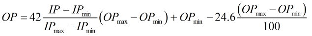
| Where | ||
|---|---|---|
| IP | = | Transmitter input value |
| IPmax | = | Transmitter maximum input value |
| IPmin | = | Transmitter minimum input value |
| OPmax | = | Upper range output value (which corresponds to the set maximum input value) for the instrument being calibrated |
| OPmin | = | Lower range output value (which corresponds to the set minimum input value) for the instrument being calibrated |