Temperature Transmitter Calibration
Form
Form: K203 – BS EN60751:1996/BS 1904 – PRT Calculation
Form Reference: C193
Purpose
The purpose of this test is to check the applied temperature matches the temperature reading on the flow computer.
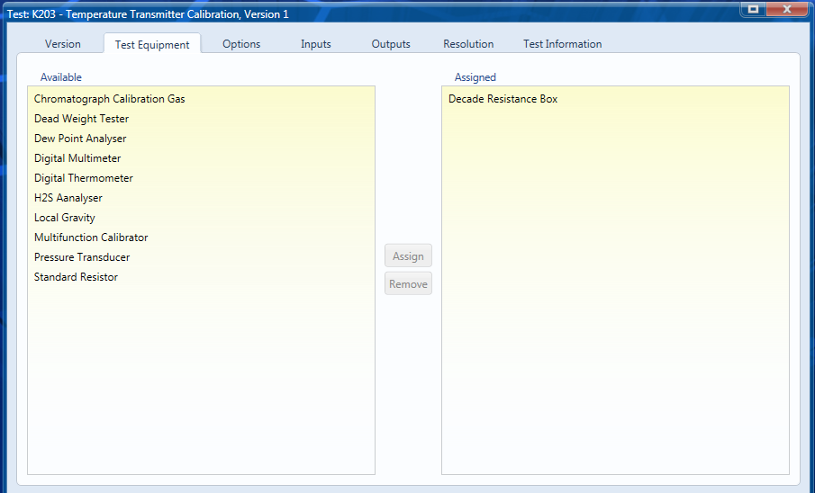
Test Equipment
A decade resistance box is to be used so is selected on the test equipment form. This will be used to simulate the applied temperature.
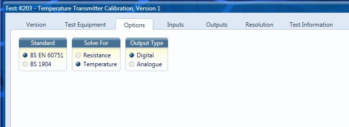
Options
In this example we are using BS EN 60751 so we select this option as the reference standard. The output will be digital as we are reading the temperature value as displayed by the flow computer.
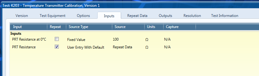
Inputs
The applied resistance will be repeated as we will perform checks at increments throughout the range of the transmitter. Resistance values to be input can be set in the Repeat Data tab if fixed or user entry with default is selected in the source type drop down menu. They can also be input from a piece of equipment if the data is input into the selected piece of test equipment. Otherwise they can be user entered when the test is run.
The resistance at 0°C will be fixed to 100 Ω.
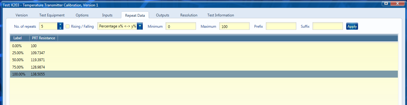
Repeat Data
This test will be carried out over 5 points over a range of 0-100°C, corresponding resistances have been added. The labels can be set automatically by selecting the options shown and clicking the ‘Apply’ button.
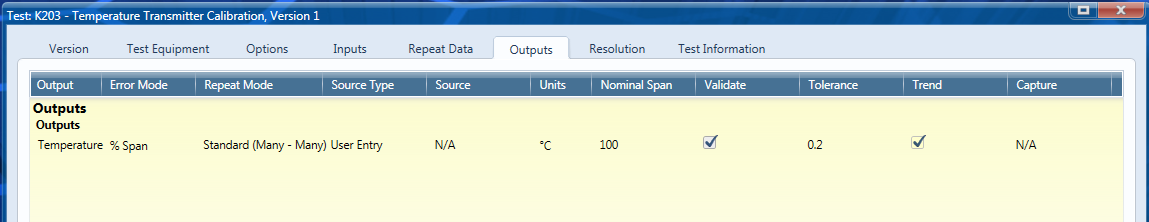
Outputs
This form only has the one output, temperature.
The error mode used for this test is percentage of span
The repeat mode is the Standard (Many to Many) we will have a different temperature output for each resistance input.
The units will be set to degrees Celsius by default.
The nominal span needs to be manually entered and is 100°C.
A typical tolerance for a temperature transmitter calibration will be 0.2 % of span.