Configuration General
Systems, Sections and Tags
Instrument Management is designed to be configured to match your measurement system.
A hierarchical system is used to identify instruments using Sites, Systems, Sections and Tags.
As these elements are used across KMM applications including Electronic Logbook and Meter Performance Manager they are configured under the administration section of KMM which is accessed by clicking on the Administration button of the main application window
Tests
Tests are configured for each instrument Tag. Historically, use of the terms Test and Calibration have been interchangeable within Instrument Management.
Tests may refer to the process of:
- Comparing the reading from a field instrument such as a pressure transmitter or temperature element with a known value from a reference standard;
- Checking a calculation performed by a flow computer system against a value which has been calculated by Instrument Management;
- Performing a series of predefined checks and recording the outcome by entering values or answering questions.
Instrument Management contains a library of test forms which can be configured to match the test procedure and tolerance in place. Each test form within Instrument Management is based on a calculation from the KELTON common Calculation Library KCCL. Calculations within Instrument Management are referenced using a unique K Number.
The steps for configuring Test forms follow the same structure.
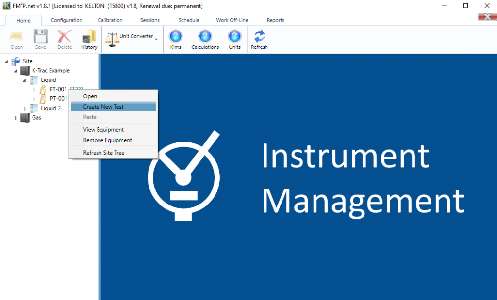
Select the test
Right-click on the tag for the instrument the test will be performed on and choose Create New Test from the shortcut menu to open up the Test Library.
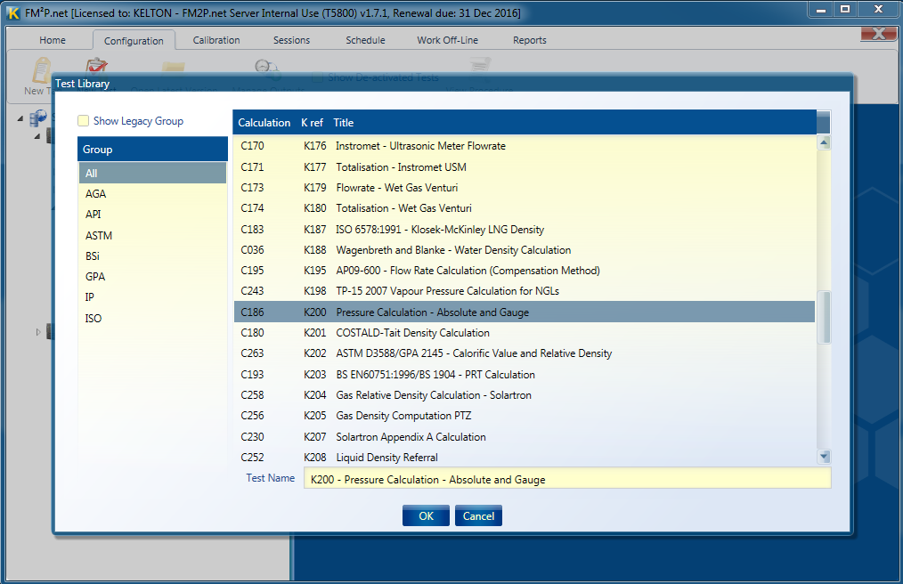
Tests in the library are grouped into categories to identify the standards uses, It the test does not pertain to a specific standard it can be found in the All group. The Legacy Group contains calculations which have been superseded and is hidden by default.
The calculation required can be selected and the name changed for the test.
In this example a test is being configured to calibrate a digital pressure transmitter using a deadweight tester. As the same base form K200 can be configured for analogue or digital pressure transmitters, differential pressure transmitters or gauges the name is edited to reflect the forms use for this tag. When editing a test name it is good practice to keep the K number intact so the original form can be easily identified.
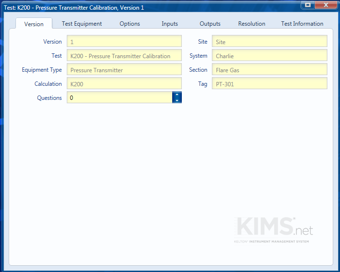
Version
The version tab displays information on the test and the tag on which it has been configured.
This tab also has the option for selecting the number of questions which may be asked during the test if applicable.
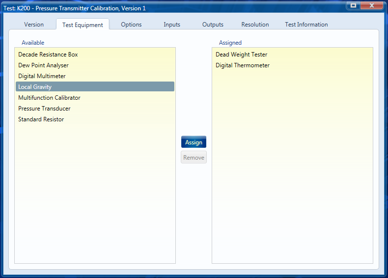
Test Equipment
This section is used to select the type of test equipment which is used for the test. The actual item of equipment will be selected when the test is executed. Assigning equipment types to a test will enable the passing of parameters from the equipment record.
To assign a type of test equipment select it from the available list (left hand pane) and click the Assign button, to remove an item of test equipment select it from the assigned list (right hand pane) and click the Remove button
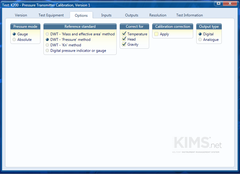
Options
Calculations may have a number of options which control how the calculation is performed and the inputs which are required, selecting one option may turn on other groups of options.
In this case we are calibrating a Gauge pressure transmitter using a deadweight tester which has been calibrated using the pressure generated method, the output of the transmitter is digital and we have chosen to correct for Temperature, Head and Gravity.
For information of the options associated for each calculation go to the help file for the calculation.
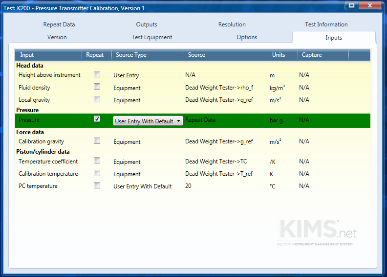
Inputs
The required inputs are dependent on the options selected.
- Repeat – Enables repeat data to be used for input.
- Source Type – This field is used to determine where the inputs will be sourced from when a calibration is performed.
- Fixed Value – Use this if the input value doesn’t change. Note a fixed value cannot be altered whist executing a calibration.
- User Entry – Use this if input value is to be entered by the user.
- User Entry with Default – Use this if input value is usually a set value but may change periodically. This value can be changed by the user when executing tests.
- OPC Server – Use this if the input value is to be drawn though OPC.
- Equipment – Use this if the input value is to come from a piece of test equipment. Note the relevant piece of equipment must be added on the Test Equipment tab for this option to become available.
- Source – This is used to specify the source of the input value, it is set to N/A if user entry is selected. If it is from a fixed value or user entry with default the input value is to be entered whilst configuring the test. For other sources a dropdown list will appear where the relevant OPC tag, Beamex output or calculation output can be selected. Note that OPC and Beamex connections need to be set up using K-Link.
- Units – Clicking on this will bring up a dropdown list from which the necessary units can be selected.
- Capture – This is enabled if OPC is selected as the Source Type, there is the choice to capture the output on load, on demand, on start or on end.
OPC Data
If the Source type uses OPC tags then these will need set up beforehand. See link OPC Connections for setup info.
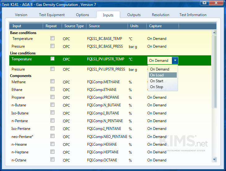
You can select to capture the data on load, on demand, on start or on end.
If it’s captured on load then when you run a calibration this data should load at the same time as the test loads.
On start means the data will be captured when the test is run.
On demand is a feature that will let you capture the data at any point during the calibration. This may be useful as the flow rate, for example, may not be stable at the start of the test so it would be better to capture the data once the test conditions have settled.
On end simply captures the data at the end of the calibration.
Repeat Data
This tab will only be visible if the user has changed the Repeat checkbox of an input is ticked on. Once the tab has been chosen, the following form will appear:
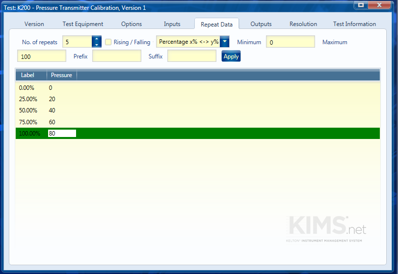
- No. of Repeats – Use the spinner control to enter the number of repeats for the input.
- Rising/Falling – Select this if the inputs are to rise and then fall again. For example, if Rising/Falling had been selected in the above form, the inputs could be:
- 0.00%
- 50.00%
- 100.00%
- 50.00%
- 0.00%
- Auto Text – Use this button to enter repeat names quickly. The options available are:
- Test #n – the repeat names will change to this text with n replaced with the number of the repeat.
- Percentage x% ↔ y% – a dialog box will appear asking the user to enter a minimum percentage. Once a number has been entered, a further dialog box will appear asking the user for a maximum percentage. Once this has been entered, the repeat names will range from the minimum to the maximum.
- Range x ↔ y – The Range x ↔ y works in a similar way except the user should enter a number instead of a percentage.
- Prefix/Suffix – Use these sections to enter text before and after the repeat name. This saves typing the same entry more than once.
- Label – This section will display the repeat name. This can be entered by typing in the box or by selecting an option from the Auto Text feature as described above.
Outputs
The Outputs tab shows the outputs that are displayed when the test, as configured, is run.
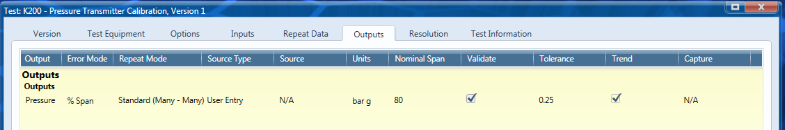
On the output tab itself there are several fields:
- Output – Name of the output, this cannot be edited
- Error Mode – Sets the type of error that will be applied to the output from a selection of:
- Difference
- % Reading
- % Calculated
- % Span
- Repeat Mode – If an input has been set to repeat a repeat mode will need to be selected from the following:
- Standard (Many – Many) – Each calculated value is validated against a corresponding actual value. Use this where each answer should be different. e.g. 0%-100% range of a transmitter.
- Many – One – Each calculated value is validated against the same actual value. Use this where each answer should be the same. e.g. Run #1-3 of a Gas Chromatograph.
- Average – One – Calculated values are used to form an average value which is then validated against a single actual value. This can be used when a signal can vary beyond tolerance but on average over time it should be within tolerance.
- Standard Deviation – One – The standard deviation of the calculated values is taken and validated against a single actual value.
- Standard Uncertainty – One – The standard uncertainty of the calculated values is taken and validated against a single actual value. Standard uncertainty is the Standard Deviation divided by the mean value.
- Extended Uncertainty – One – The extended uncertainty of the calculated values is taken and validated against a single actual value. Expanded uncertainty is the standard uncertainty multiplied by a coverage factor, the default of which is 2.
- Source Type – Is used to specify where the actual values, which will be used for validation, are coming from. Options include:
- Fixed Value – Use this if the actual value doesn’t change.
- User Entry – Use this if actual value will be entered by the user.
- User Entry with Default – Use this if actual value is usually constant but may change periodically.
- OPC Server – Use this if the actual value is drawn though OPC.
- Beamex – Use this if the actual value will be input via a Beamex.
- Calculated Value – Use this if the actual value is to be calculated using alternative methods e.g. this can be used for a totalisation calculation by entering the start and end totals displayed by the flow computer
- Source – This enables the actual value to sourced, it is set to N/A if user entry is selected. If it is from a fixed value or user entry with default the actual value is to be entered whilst configuring the test. For other sources a dropdown list will appear where the relevant OPC tag, Beamex output or calculation output can be selected. Note that OPC and Beamex connections need to be set up using K-Link.
- Units – Clicking on this will bring up a dropdown list from which the necessary units can be selected.
- Nominal Span – This is only needed if the Error Mode selected is % Span, enter the span across which the measurements will be taken.
- Validate – Make sure boxes are checked for the outputs that you want to validate.
- Tolerance – Sets the tolerance that the error cannot exceed. (The tolerance can be taken from the uncertainty analysis)
- Trend – Use this to set which output will be shown when the test is displayed in the calibration history.
- Capture – This is enabled if OPC is selected as the Source Type, there is the choice to capture the output on load, on start or on end.
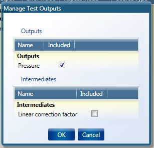
The outputs can be modified by clicking on the Manage Outputs button on the Configuration ribbon. This opens up a window which enables outputs to added from the intermediates section of the calculation, outputs can also be excluded from the results by unchecking the Included checkbox.
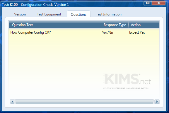
Questions
If 1 or more questions have been added in the Version tab, then the Questions tab will appear. Type the desired question(s) into the Question Text field. A number of Response Types are available as follows:
- Yes/No – The user will answer this question from a drop down box with either ‘Yes’ or ‘No’.
- Text – The user will answer this question with text.
- None – There will be no answer for this, this can be used to space questions or as headers for grouping questions or just for information.
- Integer – The user will answer this question with a whole number.
- Double – The user will answer this question with a number that is not an integer (a number with decimal places).
- Date – The user will answer this question with a date selected from a calendar tool.
- Time – The user will answer this question with a time, either typed or selected by clicking up or down arrows.
For a Yes/No type question a pass/fail criteria can be added.
- Expect Yes – The pass criteria for this question is Yes. If No is answered the test will fail.
- Expect No – The pass criteria for this question is No. If Yes is answered the test will fail.
- Ignore – There is no pass or fail criteria for this question.
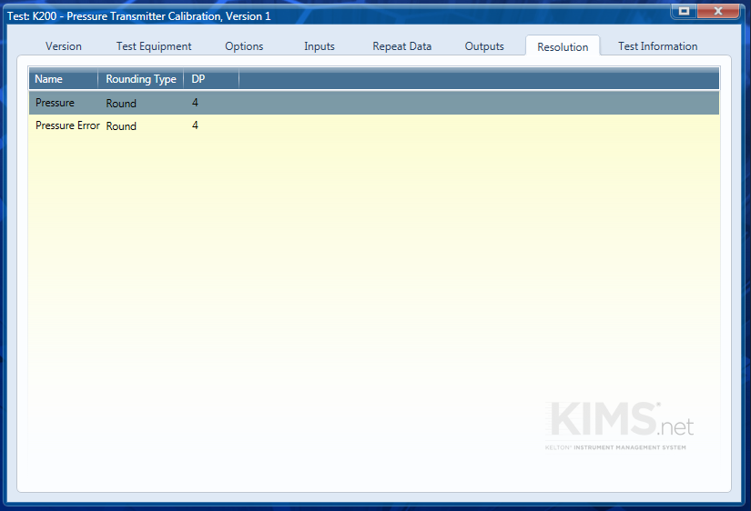
Resolution
The resolution displayed in the results can be altered using this tab. Outputs and their associated error can be rounded or truncated to an appropriate number of decimal places. To change the number of decimal places displayed type a number between 0 and 15 into the DP field. The Rounding Type field is used to select between rounding or truncation of the result to the desired number of decimal places.
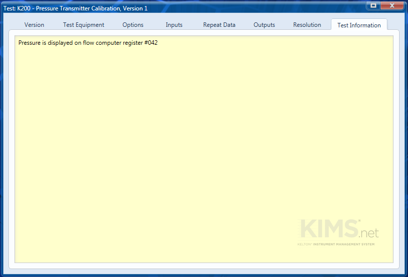
Test Information
The Test Information tab can be used to add any relevant information to the test that may be of use to those who will be using it to perform calibrations or anyone who has to reconfigure it at a later date.