C270 – ISO 5167 Orifice Mass Flow Calculation
Description
This calculates the mass flow rate for orifice plate metering systems according to the ISO 5167 standard.
References
ISO 5167: Measurement of fluid flow by means of pressure differential devices inserted in circular cross-section conduits running full
ISO TR9464: Guidelines for the use of ISO 5167
ISO TR15377: Measurement of fluid flow by means of pressure differential devices – Guidelines for the specification of orifice plates, nozzles and venturi tubes beyond the scope of ISO 5167
BS 1042: Part 1. Pressure differential devices – Section 1.2 Specification for square-edged orifice plates and nozzles (with drain holes, in pipes below 50mm diameter, as inlet and outlet devices) and other orifice plates and Borda inlets (1984)
Kelton calculation reference C270
FLOCALC calculation F068: ISO 5167-1:1991 – Orifice Calculation
FLOCALC calculation F069: ISO 5167-1:1998 Amd 1 – Orifice Calculation
FLOCALC calculation F070: ISO 5167-2:2003 – Orifice Calculation
KIMS calculation K215: ISO 5167 Orifice Plate Calculations
FLOCALC calculation F037: Upstream Density Calculation
Options
Standard version
- 1991
- 1998
- 2003
This option group allows selection of the revision of the standard wished to be employed.
Tapping Type
- Flange
- D/D2
- Corner
This option group allows the selection of the tapping type used for the pressure measurements on the orifice plate system.
Drain Hole
- None
- BS 1042
This option allows for selection of a drain hole correction according to BS 1042.
Fluid
- Gas
- Liquid
This option allows selection of whether the fluid is a liquid or a gas. If gas is selected more options are needed to carry out the calculation suitably.
Expansibility factor
- User entered
- Calculated
This option give the choice of calculating expansibility or entering a known value.
Temperature
- Upstream
- Downstream
This option allows selection of where the temperature is measured, upstream of the orifice plate meter or downstream where the flow has fully recovered.
Temperature Referral
- Isentropic
- Isenthalpic
This option group will appear if downstream temperature is selected. It allows a choice between an isentropic or an isenthalpic correction to upstream temperature. Note the isenthalpic option should be selected when using ISO 5167:2003.
Joule-Thomson Coefficient
- User entered
- Calculated
This option group will appear if an isenthalpic correction to upstream temperature is selected, it allows the Joule-Thomson coefficient to be entered if the value is known or calculated by Reader-Harris’ simplified equation if otherwise.
Density
- Upstream
- Downstream
This option group allows selection where the density measurement is taken, upstream of the orifice plate or downstream at pressure, p2, and temperature T3.
Density Referral
- Isentropic
- Isenthalpic
This option group will appear if the downstream density option is selected. It allows a choice of whether density is corrected to upstream conditions using an isentropic or isenthalpic (PTZ) correction as shown in F037.
Calculation
Mass Flow Rate
The mass flow rate is calculated by:
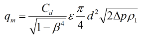
| Where | ||
|---|---|---|
| Cd | = | Coefficient of discharge |
| β | = | Diameter ratio |
| ε | = | Expansibility factor |
| d | = | Orifice bore |
| Δp | = | Differential pressure |
| ρ1 | = | Upstream density |
Coefficient of discharge
If the standard selected is the 1991 specification the Stolz equation is used to calculate discharge coefficient.
If the standard selected is the 1998 or 2003 specification the Reader-Harris/Gallagher equation is used to calculate discharge coefficient.
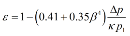
Expansibility Factor
If the standard being used is the 1991 or 1998 specification then expansibility factor is calculated by:
If the standard being used is the 2003 specification then expansibility factor is calculated by:
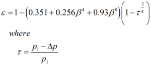
If the fluid is a liquid the expansibility factor will be equal to 1 as the flow is assumed to be incompressible.
Pressure Loss
If the standard selected is the 1991 or 1998 specification then the permanent pressure loss is calculated by:
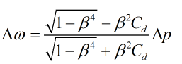
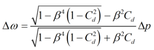
If the standard selected is the 2003 specification then the permanent pressure loss is calculated by:
Temperature Referral
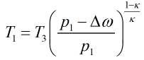
If an isentropic temperature referral is selected then upstream temperature is calculated by:
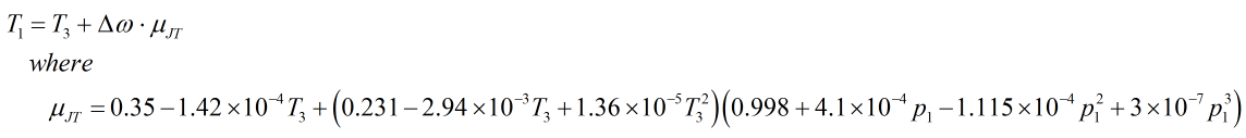
If an isenthalpic correction is applied:
| Where | ||
|---|---|---|
| p1 | = | Upstream pressure |
| κ | = | Isentropic exponent |
| T3 | = | Recovery point temperature |
| Δω | = | Permanent pressure loss |
| μJT | = | Joule-Thomson coefficient |