BL-701 – Prover
Description
This block calculates the uncertainty in proving. The block can be configured for proving with a volume prover, master meter or a combination of the two.
Options
Prover
- Volume Prover
- Master Meter
- Volume Prover + Master Meter
This option is used to select the type of prover being used for the metering system.
Volume prover
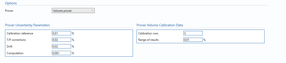
Prover Uncertainty Parameters
- Calibration reference – Uncertainty in calibration reference device.
Note: For example this could be water draw or gravimetric system.
- T/P corrections – Uncertainty due to temperature and pressure corrections for prover during prover calibration.
- Drift – Maximum drift in prover volume between calibrations.
Note: Can only get this from repeat calibration data.
- Computation – Uncertainty due to computational errors in flow computer.
Note: Negligible term included for completeness – assume 0.001%.
Prover Volume Calibration Data
- Calibration runs – Number of consecutive calibration runs used to determine the average prover volume.
Note: Default (and suggested minimum) is 3 runs.
- Range of Results – The range between the maximum and minimum prover volumes obtained in individual runs.
Master meter
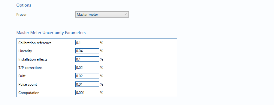
Master Meter Uncertainty Parameters
- Calibration reference – Uncertainty in prover base volume or in (external) calibration facility flowrate.
- Linearity – Meter linearity, taken from calibration data or meter specification.
- Installation effects – Uncertainty due to different piping configurations between calibration laboratory and installed location.
- T/P corrections – Uncertainty due to temperature and pressure corrections for master meter during prover calibration.
- Drift – Maximum drift in K-factor between calibrations.
Note: Can only get this from repeat calibration data.
- Pulse count – Uncertainty due to number of pulses collected.
Note: Default 0.01%.
- Computation – Uncertainty due to computational errors in flow computer.
Note: Negligible term included for completeness – assume 0.001%.
Volume prover + Master meter
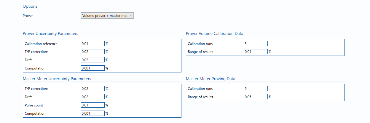
Prover Uncertainty Parameters
- Calibration reference – Uncertainty in calibration reference device.
Note: For example this could be water draw or gravimetric system.
- T/P corrections – Uncertainty due to temperature and pressure corrections for prover during prover calibration.
- Drift – Maximum drift in prover volume between calibrations.
Note: Can only get this from repeat calibration data.
- Computation – Uncertainty due to computational errors in flow computer.
Note: Negligible term included for completeness – assume 0.001%.
Prover Volume Calibration Data
- Calibration runs – Number of consecutive calibration runs used to determine the average prover volume.
Note: Default (and suggested minimum) is 3 runs.
- Range of Results – The range between the maximum and minimum prover volumes obtained in individual runs.
Master Meter Uncertainty Parameters
- Calibration reference – Uncertainty in prover base volume or in (external) calibration facility flowrate.
- Linearity – Meter linearity, taken from calibration data or meter specification.
- Installation effects – Uncertainty due to different piping configurations between calibration laboratory and installed location.
- T/P corrections – Uncertainty due to temperature and pressure corrections for master meter during prover calibration.
- Drift – Maximum drift in K-factor between calibrations.
Note: Can only get this from repeat calibration data.
- Pulse count – Uncertainty due to number of pulses collected.
Note: Default 0.01%.
- Computation – Uncertainty due to computational errors in flow computer.
Note: Negligible term included for completeness – assume 0.001%.
Master Meter Proving Data
- Calibration runs – Number of consecutive calibration runs used to determine the average prover volume.
Note: Default (and suggested minimum) is 5 runs.
- Range of Results – The range between the maximum and minimum prover volumes obtained in individual runs.
Calculations
Prover Volume flow rate
The uncertainty calculation for the prover/master meter volume flow rate is detailed in the uncertainty budget table giving a break down of how the overall uncertainty is calculated.
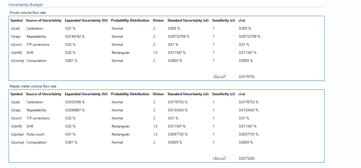
The values input into the uncertainty budget are taken from the uncertainty components calculated in this block from the calculation inputs. These values are taken in as the expanded uncertainties and are divided by a coverage factor to gain the standard uncertainty.
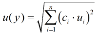
The coverage factor is determined by the probability distribution that best suits that uncertainty component. The standard uncertainty is then multiplied by the sensitivity value then squared. This is done for each component that contributes to the overall uncertainty in prover/ master meter volume flow rate. The Standard Uncertainty in volume flow rate is the square root of the sum of each component variance as shown in the following equation:
Calculated Uncertainty
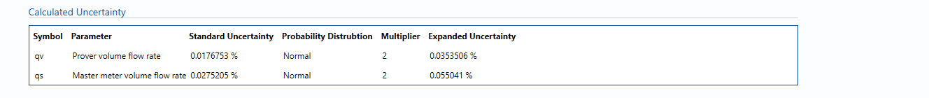
The Expanded Uncertainty is the Standard Uncertainty multiplied by the coverage factor (k). The coverage factor is defaulted to k = 2 (equivalent to a confidence level of approximately 95%).
The Relative Uncertainty is the Expanded Uncertainty divided by the Prover/ Master meter volume flow rate depending on the parameter.
References
Standards
ISO 5168:2005 – Measurement of fluid flow – Procedures for the evaluation of uncertainties
ISO Guide 98-3 – Uncertainty of measurement – Part 3: Guide to the expression of uncertainty in measurement (GUM:1995)