BL-401 – Turbine Meter with Oil Prover
Description
This block calculates the uncertainty in oil flow rate through a proved turbine meter.
Inputs
Meter Proving Data
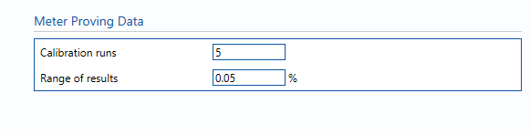
Calibration runs – Number of consecutive proves used to determine the average meter K-Factor. Default (and suggested minimum) is 5 runs.
Range of results – The range between the maximum and minimum K-Factors obtained in individual runs (100 x (max-min)/ave).
Uncertainty Parameters
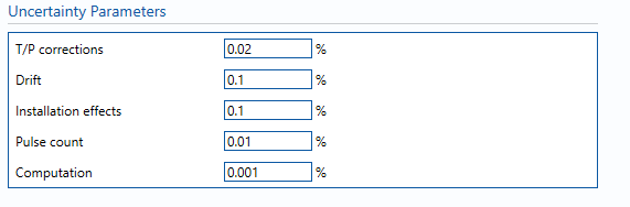
T/P corrections – Uncertainty due to Ct and Cp corrections for prover (or master meter) and test meter.
Drift – Maximum likely drift in meter K-factor between calibrations. Can only get this from repeat calibration data. If not available assume 0.05%.
Installation effects – Uncertainty due to installation effects caused by varying operating scenarios
Pulse count – Uncertainty due to number of pulses counted during proving. Negligible term included for completeness, assume 0.01%.
Computation – Uncertainty due to computational errors in flow computer. Negligible term included for completeness, assume 0.001%.
Calculations
The volume flow rate is taken from the Input/Output tab whilst the standard volume & mass flow rates are calculated from the volume flow rate using the VCF and line density respectively.
The VCF and line density values and their associated uncertainties are taken from the block BL-016 – Oil VCF.
The units selected for parameters on the Input/Output tab will be applied globally throughout the uncertainty module in use. They will be applied to values used in the uncertainty budget. Inputs that are local to this block can have their units altered within the block.
Volume flow rate
The uncertainty calculation for the volume flow rate is detailed in the first uncertainty budget table giving a break down of how the overall uncertainty is calculated.
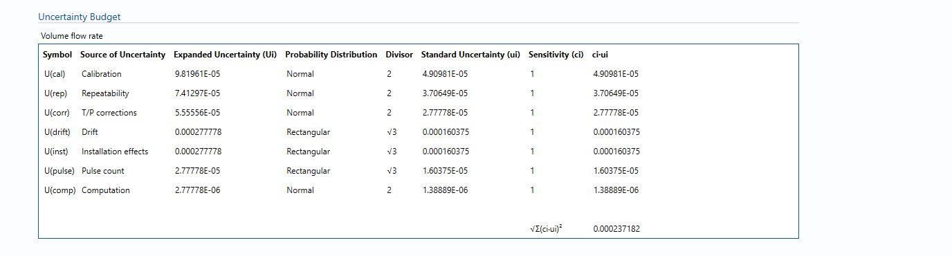
The values input into the uncertainty budget are taken from the uncertainty components calculated in this block from the calculation inputs. These values are taken in as the expanded uncertainties and are divided by a coverage factor to gain the standard uncertainty.
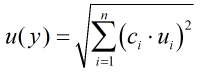
The coverage factor is determined by the probability distribution that best suits that uncertainty component. The standard uncertainty is then multiplied by the sensitivity value then squared. This is done for each component that contributes to the overall uncertainty in volume flow rate. The Standard Uncertainty in volume flow rate is the square root of the sum of each component variance as shown in the following equation:
Calculated Uncertainty
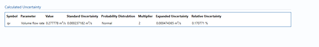
The Expanded Uncertainty is the Standard Uncertainty multiplied by the coverage factor (k). The coverage factor is defaulted to k = 2 (equivalent to a confidence level of approximately 95%).
The Relative Uncertainty is the Expanded Uncertainty divided by the volume flow rate/ standard volume flow rate/ mass flow rate depending on the parameter.
References
Standards
ISO 5168:2005 – Measurement of fluid flow – Procedures for the evaluation of uncertainties
ISO Guide 98-3 – Uncertainty of measurement – Part 3: Guide to the expression of uncertainty in measurement (GUM:1995)
Uncertainty Blocks