B014 – Measured Relative Density
Description
This block calculates the uncertainty in relative density measured by a specified RD analyser. The appropriate RD analyser should be selected from the drop down boxes and other inputs should be entered as per data sheets.
Options
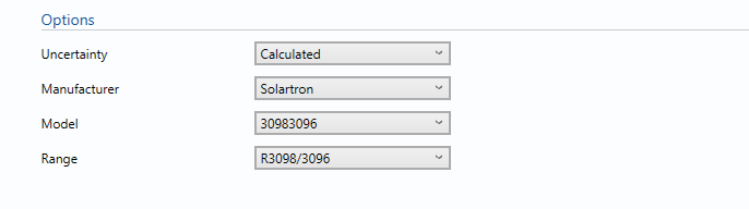
The RD analyser manufacturer, model and range are selected from the drop down boxes.
In this section, a wide variety of inputs are given based on KELTON’s experiences.
Uncertainty
If the measure relative density is measured using RD analyser select calculated, otherwise select user entered to enter the estimated expanded uncertainty in the measured relative density.
Manufacturer
Select the Manufacturer of the RD analyser from the given list.
Model
Select the Model of the RD analyser.
Range
Select the Range (If Specified by the manufacturer data sheet)
Inputs
The RD analyser characteristics are inputted from the manufacturer’s data sheets.
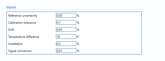
Reference uncertainty
The uncertainty in the calibration reference of the RD analysers.
Calibration tolerance
Maximum tolerance allowed during calibration process. (Taken from calibration records where available, assumed otherwise).
Note: Typical value is between ± 0.05% of span to ±0.15% of span.
Drift
Average drift observed or expected between calibrations. (Taken from calibration records where available, assumed otherwise).
Note: Typical value is between ± 0.05% to ±0.15% of reading.
Calibration temperature
Temperature at which the RD analyser was calibrated.
Installation effect
Uncertainty due to installation effects such as vibration, insulation levels, etc.
Note: a typical value would be 0.1%.
Signal conversion
Uncertainty due to frequency signal conversion.
Note: a typical value would be 0.01%.
Calculations
When the RD analyser is selected, the relevant uncertainty components from the specification sheet are used for the uncertainty calculation.
The measured relative density value for which the uncertainty to be calculated is taken from the Input/Outputs tab.
Uncertainty Budget
The uncertainty calculation is detailed in the uncertainty budget table giving a breakdown of how the overall uncertainty is calculated.
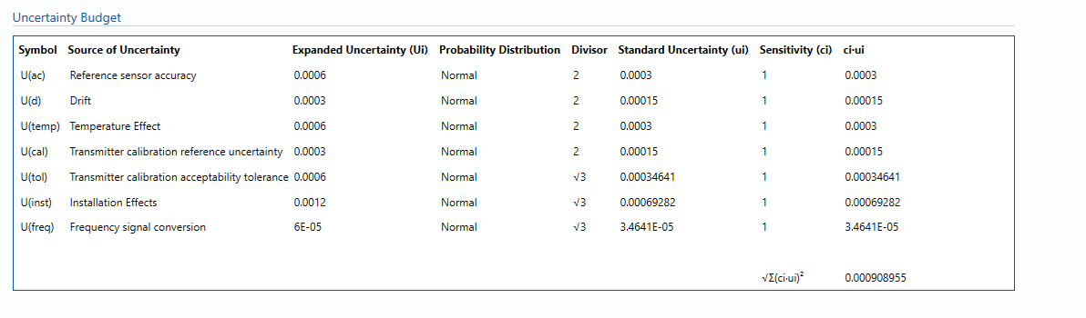
Uncertainties associated with these values are taken in as the Expanded Uncertainties. The Standard Uncertainty is calculated from dividing the Expanded Uncertainty by the coverage factor which is determined by the probability distribution that best suits that uncertainty component.
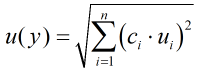
The Standard Uncertainty is then multiplied by the sensitivity value then squared. This is done for each parameter that contributes to the overall uncertainty in the measured relative density. The Standard Uncertainty in the measured relative density is the square root of the sum of each component variance as shown in the following equation:
Calculated Uncertainty
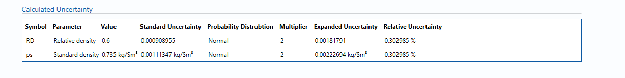
The Expanded Uncertainty is the Standard Uncertainty multiplied by the coverage factor (k). The coverage factor is defaulted to k = 2 (equivalent to a confidence level of approximately 95%). The Relative Uncertainty is the Expanded Uncertainty divided by the measured density.
‘’Note: To get the standard density for a gas multiply the relative density by the relative density of air and to get the standard density of liquid multiply the relative density by the relative density of water.’’
References
Standards
ISO 5168:2005 – Measurement of fluid flow – Procedures for the evaluation of uncertainties
ISO Guide 98-3 – Uncertainty of measurement – Part 3: Guide to the expression of uncertainty in measurement (GUM:1995) (2008)
Manufacturer documentation
Transmitters
RD analysers are available for selection from the following manufacturers: