B003 – Temperature
Description
This block calculates the uncertainty in temperature for a specified temperature transmitter. The temperature transmitter should be selected from the drop down boxes and other inputs should be entered depending on the type of the temperature transmitter used.
Transmitter
The temperature transmitter class, signal, manufacturer, model and element are selected from the drop down boxes.
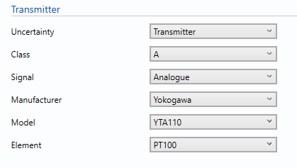
Uncertainty
If temperature is measured using a transmitter select ‘Transmitter’, if temperature is measured using a PRT connected directly to the flow computer (i.e. no transmitter) select ‘PRT only’, otherwise select ‘User entered’ to enter the estimated expanded uncertainty in temperature.
Class
- AA
- A
- B
This option is used to select the tolerance class of the temperature element.
Signal
- Analogue
If analogue is selected the uncertainty in Detector resistance tolerance and ADC resolution will be included.
- Digital
Select this option where the output of the transmitter is digital
For example: HART
Manufacturer
Select the Manufacturer of the temperature transmitter from the given list.
Note: if the manufacturer of the transmitter is not shown select unspecified and contact KELTON for further information.
Model
Select the Model of the temperature transmitter.
Element
Select the element the temperature transmitter is under according to the manufacturer data sheet.
Inputs
The temperature transmitter characteristics are inputted from the manufacturer’s data sheet.
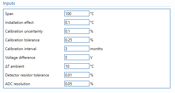
Span
Enter the span which the temperature transmitter is set to.
Installation effect
The change in temperature due to the immersion depth or Uncertainty due to installation effects, such as thermal gradients across the PRT and poor heat transfer to PRT from process fluid.
Note: The typical value would be 0.1°C as that is the calibration at full immersion.
Calibration uncertainty
Enter the uncertainty percentage in the calibration reference.
Calibration tolerance
Enter the Maximum tolerance allowed during calibration process. (Taken from calibration records where available, otherwise assumed).
Typical value is between ± 0.15% of span to ±0.25% of span.
Calibration interval
Number of months between each calibration.
Voltage difference
Difference in supply voltage between calibration and operation of the transmitter.
Temperature difference
Difference in ambient temperature between calibration and operation of the transmitter.
Detector resistance tolerance
The tolerance in the flow computer resistor used for ADC conversion.
Note: this input is only applied for analogue transmitters.
ADC resolution
The maximum tolerance allowed during ADC signal checks.
Note: this input is only applied for analogue transmitters.
Drift / year (PRT only)
The estimated drift per year.
Calculations
When a transmitter is selected, the relevant uncertainty components from that transmitter’s specification sheet are used for the uncertainty calculation.
Note: the uncertainty budget that it uses Δ°C rather than °C for uncertainty values to avoid calculation errors regarding the offset units.
Uncertainty Budget
The uncertainty budget table shows a break down of the different components that contribute to the overall calculated uncertainty.
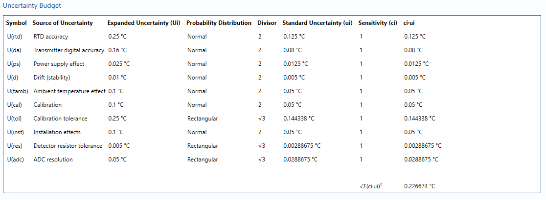
Uncertainties associated with these values are taken in as the Expanded Uncertainties. The Standard Uncertainty is calculated from dividing the Expanded Uncertainty by the coverage factor which is determined by the probability distribution that best suits that uncertainty component.
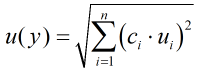
The standard uncertainty is then multiplied by the sensitivity value then squared. This is done for each parameter that contributes to the overall uncertainty in temperature. The Standard Uncertainty in temperature is the square root of the sum of each component variance as shown in the following equation:
Calculated Uncertainty

The Expanded Uncertainty is the Standard Uncertainty multiplied by the coverage factor (k). The coverage factor is defaulted to k = 2 (equivalent to a confidence level of approximately 95%).
References
Standards
ISO 5168:2005 – Measurement of fluid flow – Procedures for the evaluation of uncertainties
ISO Guide 98-3 – Uncertainty of measurement – Part 3: Guide to the expression of uncertainty in measurement (GUM:1995) (2008)
IEC 60751 – Industrial platinum resistance thermometers and platinum temperature sensors (2008)
Manufacturer documentation
Transmitters
Temperature transmitters are available for selection from the following manufacturers:
No Transmitter (PRT Only)