B001 – Pressure
Description
This block calculates the uncertainty in pressure for a specified pressure transmitter. The pressure transmitter characteristics should be selected from the drop down boxes and other inputs should be entered depending on the type of transmitter used.
Transmitter
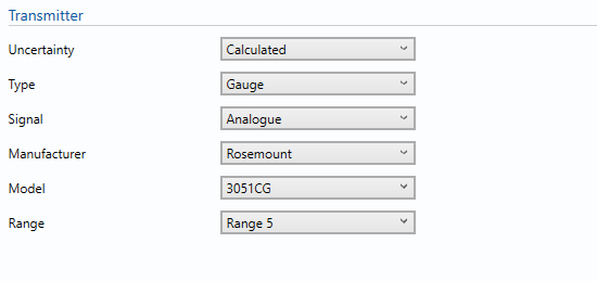
The pressure transmitter type, signal, manufacturer, model and range are selected from the drop down boxes.
In this section, a wide variety of inputs are given based on KELTON’s experiences.
Uncertainty
If pressure is measured using a transmitter select calculated, otherwise select user entered to enter the estimated expanded uncertainty in pressure.
Type
This is the type of pressure transmitter, gauge or absolute.
Signal
- Analogue
If analogue is selected the uncertainty in the detector resistance tolerance and ADC resolution will be included.
- Digital
Select this option where the output of the transmitter is digital
For example: HART
Manufacturer
Select the Manufacturer of the Pressure Transmitter from the given list.
Note: if the manufacturer of the transmitter is not shown select unspecified and enter values as per manufacturer data sheet.
Model
Select the Model of the Pressure Transmitter.
Range
Select the Range (If Specified by the manufacturer data sheet)
Inputs
The pressure transmitter characteristics are inputted from the manufacturer’s data sheets.
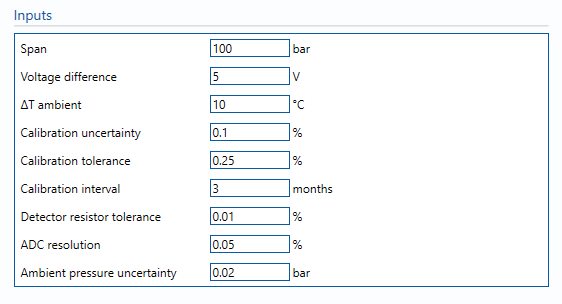
Span
Enter the span which the pressure transmitter is set to.
Note: the span plus the LRV must be lower than the URL of the transmitter and higher than the input pressure value otherwise calculation will not run and return NaN.
Lower range value
Enter the Lower range value (LRV) which the pressure transmitter is set to. By default this is 0
Voltage difference
Difference in supply voltage between calibration and operation of the transmitter.
ΔT ambient
Difference in ambient temperature between calibration and operation of the transmitter.
Calibration uncertainty
Enter the uncertainty percentage in the calibration reference to the pressure transmitter.
e.g Dead weight tester, Beamex etc.
Calibration tolerance
Enter the Maximum tolerance allowed during calibration process. (Taken from calibration records where available, otherwise assumed).
Typical value is between ± 0.15% of span to ±0.25% of span.
Calibration interval
Number of months between each calibration of the Pressure Transmitter.
Detector resistance tolerance
The tolerance in the flow computer resistor used for ADC conversion.
Note: this input is only applied for analogue transmitters.
ADC resolution
The maximum tolerance allowed during ADC signal checks.
Note: this input is only applied for analogue transmitters.
Ambient pressure uncertainty
Uncertainty due to variations in atmospheric pressure that are not accounted for in a flow computer.
Note: this input is only applied for gauge pressure transmitters.
Calculations
When a transmitter is selected and the characteristics are entered, the relevant uncertainty components from that transmitter’s specification sheet are used for the uncertainty calculations.
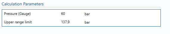
The pressure value is taken from the Input/Output tab to allow the uncertainty to be calculated for the relevant pressure.
Uncertainty Budget
The uncertainty budget table shows a break down of the different components that contribute to the overall calculated uncertainty.
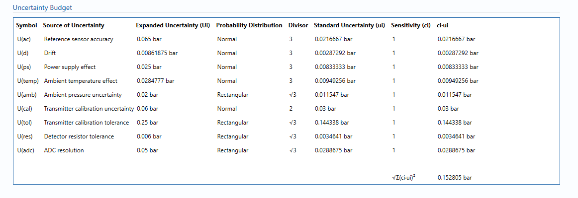
The values input into the uncertainty budget are derived from the measured pressure and the transmitter specific values relating to its calibration and specification. These values are taken in as the expanded uncertainties and are divided by a coverage factor to gain the standard uncertainty.
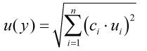
The coverage factor is determined by the probability distribution that best suits that uncertainty component. The standard uncertainty is then multiplied by the sensitivity value then squared. This is done for each component that contributes to the overall uncertainty in pressure. The Standard Uncertainty in pressure is the square root of the sum of each component variance as shown in the following equation:
Calculated Uncertainty
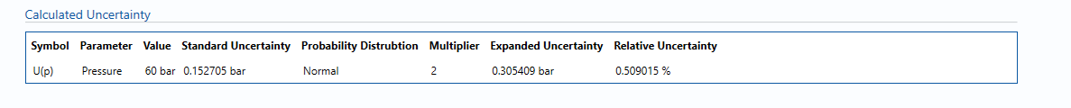
The Expanded Uncertainty is the Standard Uncertainty multiplied by the coverage factor (k). The coverage factor is defaulted to k = 2 (equivalent to a confidence level of approximately 95%).
The Relative Uncertainty is the Expanded Uncertainty divided by the Pressure.
References
Standards
ISO 5168:2005 – Measurement of fluid flow – Procedures for the evaluation of uncertainties
ISO Guide 98-3 – Uncertainty of measurement – Part 3: Guide to the expression of uncertainty in measurement (GUM:1995) (2008)
Manufacturer documentation
Pressure transmitters are available for selection from the following manufacturers: